
General Introduction to Sketcher Workbench
The main use for Sketcher is for the user to draw and define 2D sketches with accurate and rapid manner, Where it can be used later to define the solids and surfaces. As we will learn in the next drawing lessons.
We can draw 2D sketches (wireframe) through Sketcher Workbench, that can be used to generate surfaces or Solids, and the solid line font will represent it . also we can created 2D construction which uses as a tool to help to generate the solid 2D wireframe geometry.Positional constraints and geometric constraints (which are presented in green) are used to determine the position of the sketch and to control the size of the drawing sketch.
The figure Below explain what is meant by Geometric Constraints, Positional or Dimensional constraints, Wireframe Geometry, Construction Wireframe Geometry.
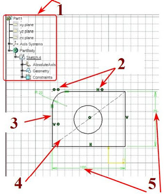
1 Specification Tree.
2 Geometric Constraints.
3 Wireframe Geometry.
4 Construction Wireframe Geometry.
5 Dimensional Constraints.

 The second one is press on the sketcher icon from any workbench that allows to generate sketches.
To learn more about how to access to any workbenches please review this Computer Aided Design Course.


The figure below explain this three methods to select a sketch plane.


1 Specification Tree.
2 Geometric Constraints.
3 Wireframe Geometry.
4 Construction Wireframe Geometry.
5 Dimensional Constraints.
To Entering to the Sketcher Workbench:
Their is tow method to enter to the Sketcher Workbench the first one is from start menu select > Mechanical Design > then choose Sketcher.
To learn more about how to access to any workbenches please review this Computer Aided Design Course.
To Edit a Node name from Specification Tree;
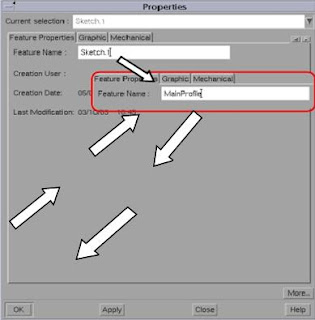
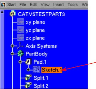
From Specification Tree we can rename the name of a node by selecting the node by mouse button 1 then click on the mouse button 3 to show the contextual menu, then you can click on the properties to display a Properties panel.


From Feature Properties tab we can see the name of the Node In the Feature Name field. Now you can change the name of the node by entering new name in the feature name field, after that you must click O.K to save changes and exit from contextual menu.
To Select a Sketch Plane:
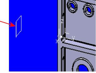
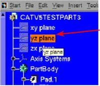
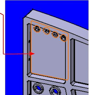
To begin drawing your sketches, firstly you must select a planar face, plane from coordinate, or an existing Sketch, after selecting the the desired plane, sketch or face the CATIA interface will turn into the sketcher workbench interface and graphic display.The figure below explain this three methods to select a sketch plane.


From the Specification Tree you can choose a Plane.


From an existing solid choose a Planar face.
From the Specification Tree you can choose an existing Sketch.
The Sketcher Workbench Interface
When accessing to the Sketcher Workbench, A new Sketch node will show in the Part of Tree, in the figure below We'll show the most important characteristics and tools, for Sketcher Workbench user interface. To become ready for drawing lessons.

1 Part tree.
2 New Sketch.
3 Standard tools.
4 Work in standard or popular view.
5 Tools for Sketcher Design.
6 Constraints Icons.
7 Exit from function.
8 Turn into 3D view.
9 Sketch Grid.
10 Sketch Axis.
11 Operations and Tools.
Before going to drawing lessons you can review this CAD lesson to learn more about the user interface for CATIA V5 program.
Drawing axes:
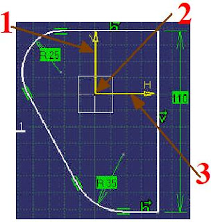
When entering to the sketcher workbench we note 2D axis ( Origin point, Vertical 'V' axis, and Horizontal 'H' axis), We can use these axes to position our design or drawing on the sketch plane by using Constraints.

1 Vertical 'V' axis.
2 Horizontal 'H' axis.
3 Origin point.
Sketcher Icons and Tool-bars
Any Computer Aided Design program containing Tool-bars and icons that make drawing process more easy and flexible, Each Workbench in the CATIA program contains its own tool-bars and in the context of the sketcher workbench there are four basic tool-bars:

1 Constraints: constraints is very important for controlling and adjusting drawing Dimensions and position.
2 Profile Creation: This is the most important Tool-bar, and it is used for the building of geometric elements and creation the drawing design. for more details review this lessons drawing profile part 1, part 2.
3 The Operations tool-bar: we can used this tool-bar, to make very important operations in the geometry, Such as: (Chamfer, Trimming, Corner, Filleting, etc.) and to manipulating geometry, Such as: ( Translating, Symmetry, Projection, Mirroring, etc.).
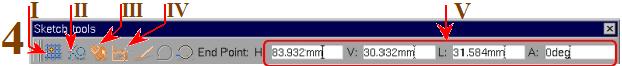
4 The Sketch Tools tool-bar: is used for controlling and adjusting drawing Dimensions and positioning the geometry by applying automatic Dimensional constraints and Automatic Geometric constraints or entering constraint value manually.
I Toggle to the Grid snapping.
II Toggle to the Construction geometry.
III Automatic Geometric constraints.
IV Automatic Dimensional constraints.
V Areas to enter the constraint value manually.
Note that, the icons with orange color indicates that the tool is activated.
If we are activate the automated geometric constraints, the geometric Permissions Must be applied to the items that is created, the automated dimension (interval) constraints are only created on chamfers or fillet radii and when insert in the related area on the Sketch tools tool-bar.
Under the Sketch node (in the specification tree) we can see all constraints.
We can deleted undesirable constraints by choosing it by MB1 and click on deleted key.

For more details about the Sketcher Icons and Tool-bars, you can review this drawing lessons, Where we explain each tool separately and in more depth.
We can selected a single sketch either from the specification tree or graphically, and by using [ Ctrl + MB2] we can selected two or more elements. In this drawing lesson we will get familiar with the selection icons, so the selection can be implemented by using [MB2] and one of the selection icons.


Note that:
I Toggle to the Grid snapping.
II Toggle to the Construction geometry.
III Automatic Geometric constraints.
IV Automatic Dimensional constraints.
V Areas to enter the constraint value manually.
Note that, the icons with orange color indicates that the tool is activated.
If we are activate the automated geometric constraints, the geometric Permissions Must be applied to the items that is created, the automated dimension (interval) constraints are only created on chamfers or fillet radii and when insert in the related area on the Sketch tools tool-bar.
Under the Sketch node (in the specification tree) we can see all constraints.
We can deleted undesirable constraints by choosing it by MB1 and click on deleted key.
For more details about the Sketcher Icons and Tool-bars, you can review this drawing lessons, Where we explain each tool separately and in more depth.
Positioning and Selecting the Sketch

1 Standard or normal selection: This icon is used to identify and select items by clicking on them, or by clicking constantly and dragging a rectangle over the items to be identified and selected, and then leave clicking to specify all the elements inside the rectangle.
2 Selection Trap: Analogous to the Standard or normal selection command except single element cannot be selected. Select by clicking constantly and dragging a rectangle over the items to be identified and selected, and then leave clicking to specify all the elements inside the rectangle.
3 Intersecting Trap: Select by clicking constantly and dragging a rectangle over the items that you want to identified and selected, All elements inside and crossing the rectangle will be selected.
4 Polygon Trap: Selection by drawing a polygon around the elements that you want to selected, by clicking on the [MB1]. Double clicking to completes the selection. Only elements inside the polygon will be selected.
5 Paint Stroke Selection: Selection by drawing a curve through the elements that you want to selected, by clicking on the [MB1]. Double clicking to completes the selection. Only elements that are crossed by the curve will be selected.
 |
| Polygon Trap |
 |
| Paint Stroke Selection |
Note that:
- In all selection cases the selected geometry will converting to the orange color.
- by clicking [MB1] anywhere on the graphics window, the selected elements will be deselect.
---------------------------------------------------------------------------
Thanks for the information auto cad services
ReplyDeleteJoin Engineers CAD Studio for the best CAD Training Programs.
ReplyDeleteComputer aided drug design software has emerged as a cornerstone in the quest for innovative and effective therapeutics, revolutionizing the way researchers conceptualize, design, and optimize potential drug candidates.
ReplyDeleteDrug design software plays a critical role in modern pharmaceutical research, facilitating the creation and optimization of new therapeutic compounds.
ReplyDelete